
Imagine the day the payload arrives. The test slot is booked, the crew is ready, and someone measures the chamber door. But the payload is two inches too wide.
Misses like that are easy to make, because chamber size gets set in layers. The payload is one. Keep-out zones add another, the shroud and fixtures add a third, and the shell wall goes on top. Then the door, the shipping route, the pump, the thermal system, and the leak-rate limit each get a vote.
When your payload is bigger than anything in a catalog, no next size up exists to bail you out. You have to build the answer from the payload outward. This guide sizes a custom vacuum chamber in that order, with the reason for each step, so you find the surprises on paper before they reach the loading dock.
Short answer: Size the vacuum chamber from the inside out. Start with the payload as it sits during the test, then add keep-out zones, the shroud and fixtures, and the shell wall. Check the door, then test the result against your vacuum level, thermal range, cleanliness class, and leak-rate limit.
Start With the Payload Envelope
Size to the payload as it sits during the test, not as it ships. Deployed arrays and extended booms make the test envelope larger than the stowed one, and a chamber sized to the stowed payload cannot test the deployed one.
Then add keep-out zones for thermal hardware, harnesses, instrumentation, and technician access. Some tests need more. An electric thruster needs open distance ahead of its exit plane. A University of Michigan dissertation names chamber size as a way to limit plasma-wall interactions from sputtering and electromagnetic coupling.
Add the Hardware That Shares the Space
The envelope and keep-out zones define the working volume, the shroud and fixtures wrap around it, and the shell wraps around all of it so usable volume is always smaller than the vessel. A good rule of thumb puts shrouds 2 to 6 inches from the side wall and platens 4 to 10 inches above the bottom.
Example with assumed numbers:
| Layer | Width after this layer |
| Payload in test setup | 8 ft |
| Keep-out zone, 1 ft per side (assumed) | 10 ft |
| Shroud panels, 2 in per side (assumed) | 10 ft 4 in |
| Shroud-to-wall gap, 2 to 6 in per side | 10 ft 8 in to 11 ft 4 in (shell inside width) |
| Shell wall, 1/2 in per side (assumed) | 10 ft 9 in to 11 ft 5 in (shell outside width) |
Check How the Payload Gets Inside
A vacuum chamber that fits the payload can still fail at the door. The opening is smaller than the vessel cross-section because of the flange and seal. Check that the payload on its handling fixture clears it, and that the floors carry the loaded weight.
Transport can also rule out a factory-built vessel. On the National Network, federal rules cap commercial vehicle width at 102 inches, or 8.5 feet, cargo included. In GAO’s 2015 tables, Florida, West Virginia, and Wisconsin list 13 ft 6 in as the legal height, but states set their own rules, so check your route.
The example vessel above is wider than 8.5 feet inside, so it moves only on an oversize permit. For vessels larger than 25ft, a field-built chamber is the option: the shell ships in sections and is welded, leak-checked, and finished on site. Decide early, since it changes the schedule and site needs.
Size for the Vacuum Level
A bigger chamber is not automatically slower to pump down. In rough and medium vacuum, pump-down time follows this equation:
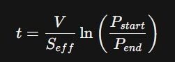
V is volume, and Seff is effective pump speed. Double the volume with the same pump and the time roughly doubles. Take a cylinder 10 ft across and 12 ft long, about 26,700 liters, with an assumed 500 L/s effective speed. Pumping from 760 to 1 Torr takes about 6 minutes. At 24 ft long, it takes about 12. Real times run longer because piping and valves cut effective speed.
In the high vacuum range, below about 10⁻³ Torr, most of the gas comes from surfaces, and the volume matters less. Material outgassing sets that gas load, and water vapor dominates it once surfaces are cleaned. Water trapped in walls, shroud, fixtures, and payload releases slowly, and that load sets base pressure. So surface area and materials set the pump size.
Screen payload materials with NASA’s outgassing database. Its figures are percent mass loss, not gas rates, so they rank materials only.
Size for the Thermal Profile
The payload sets the starting size. A NASA workshop paper states that natural convection and gas conduction are negligible in vacuum chambers, so heat moves by radiation to the shroud and by conduction through the fixture.
A payload crowded against one wall sees little else, so give it distance on all sides to even out the view factors (the share of one surface’s radiation that lands on another). That keeps ramp rate and hold temperature uniform.
Range and ramp rate can push the chamber larger still. The shroud in a TVAC chamber may run from cryogenic to well above ambient, requiring space for panels, fluid passages, and insulation.
Large vacuum chambers also layer unevenly, with gradients along long shroud circuits and between the top and bottom. Shorter parallel circuits and zone control are the usual fixes.
Set Cleanliness and Leak-Rate Limits Early
Two requirements should be fixed before the chamber size is finalized: cleanliness class and leak rate. Both impact the chamber design.
Cleanliness class. ISO 14644-1 sets classes by airborne particle concentration for sizes from 0.1 to 5 micrometers. It cannot characterize the chemical nature of particles, so write molecular-contamination limits into the spec separately. Tighter classes limit interior finish, materials, seals, and lubricants, and some change dimensions: an electropolished interior or a clean-room enclosure at the door takes more space.
Leak rate. A larger shell has more seams, so a fixed leak-rate limit gets harder to meet. A door seal on a 12-foot opening, for example, is three times as long as one on a 4-foot opening. To keep the requirement testable, state the limit as a number and name the proof method.
Three methods cover most needs. Helium spray (ASTM E498) locates leaks. A helium hood or bag test (ASTM E1603) measures the total. Rate-of-rise separates leaks from outgassing, because leak flow is constant and outgassing tapers off. Once the limit and method are set, Redline can plan welds, flanges, and test sequence around your number.
A Sizing Checklist for Your Vacuum Chamber
Before you request a quote from a custom vacuum chamber manufacturer, write down these eight items.
| # | Write down | What it decides |
| 1 | Test envelope (L x W x H) and mass, with attached support equipment | Volume, floor and rail loading |
| 2 | Keep-out zones and sightlines | Extra volume, window and port locations |
| 3 | Shroud and fixture allowance | Shell diameter or width |
| 4 | Door, floor, and handling limits at the site | Door type, floor rating, handling gear |
| 5 | Target pressure and hold time | High-vacuum pump size |
| 6 | Thermal range, ramp rate, uniformity | Shroud, chiller, and heater size |
| 7 | Cleanliness class and leak-rate limit, with test methods | Finish, materials, weld plan |
| 8 | Route, building access, rigging, utilities | Factory-built or field-built shell |
Next Steps
Each step above traces back to a number you can write down. Settle them early, and the chamber size follows from arithmetic. Leave them open, and the surprises come late, at the door or on the trailer.
If your payload doesn’t fit standard equipment, send the checklist above to Redline Chambers engineering, and we’ll size the vacuum chamber from it.